DTM92 Type Front Suspension
-
- Home > Other > Vendor offers >


supersize
supersize
supersize
-
Seller Details2.7l S14
Posts: 1,888
Registered: June 2006
Location: Germany- Feedback: None
- See Detailed Feedback
- Contact Seller
- View seller's other items
-
DTM92 Type Front Suspension
Quantity Views Date Posted 1 9717 Thu February 21, 2008
-
Asking Price Shipping Amount Condition Best Offer None Excellent
-
Description: This is late DTM92 style. It does not get any better than this for our type of suspension, except perhaps to change your struts to the DTM magnesium style housings (which is possible, but not without consequence for other systems e.g. race ABS or what not). It is the ultimate in light weight suspension, full geometry adjustability, steering precision and stiffness. This suspension will work on e30 and e36 chassis race cars and even some E46 cars have used DTM struts and suspension (see GTR class cars here in Germany). These are used successfully on championship winning rally cars under adverse conditions and they survive 24h Nuerburgring races and even some front shunts without incident.
version that bolts into bottom of STOCK front subframe (for those who do not want a custom subframe):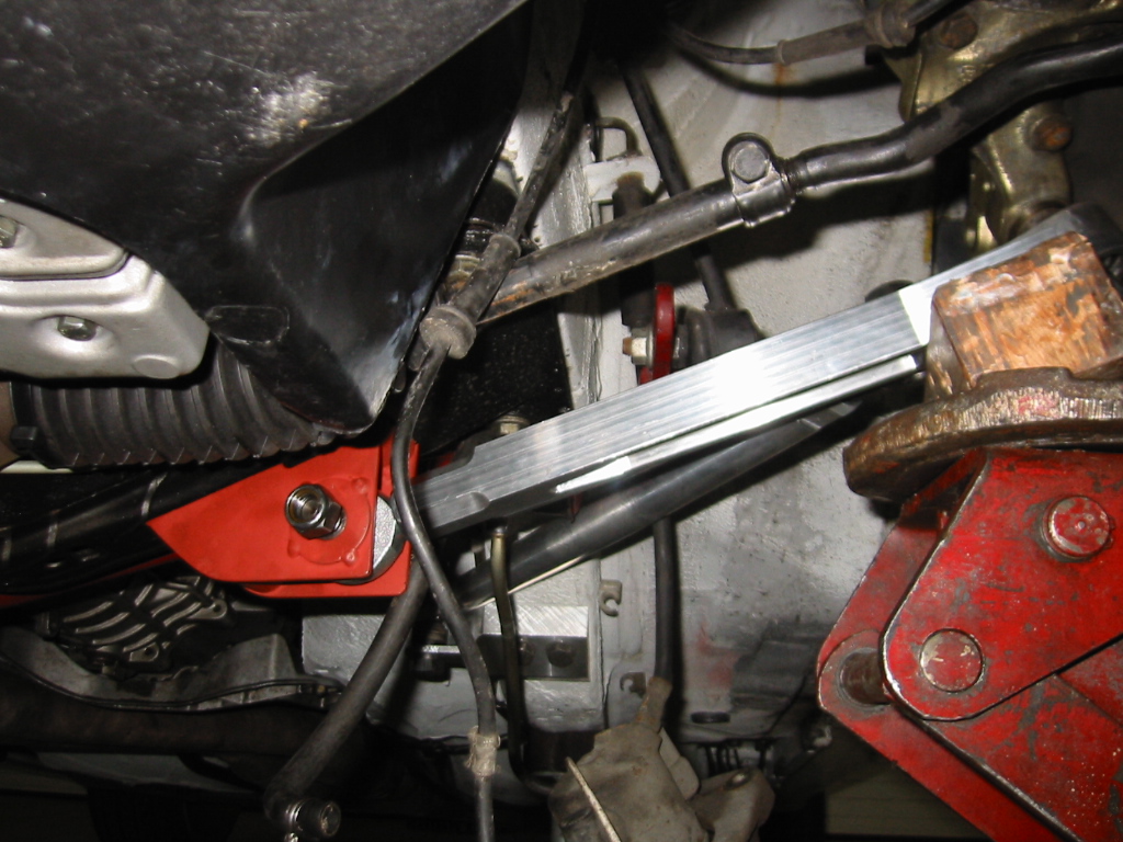
version with raised inner control arm pickup point (modified subframe for the optimal control arm geometry for lowered cars. you dont have to run such large spacers at the outer control arm pickup and it will fit your rims easier):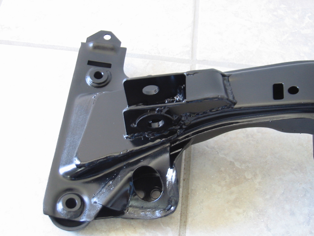
spare parts: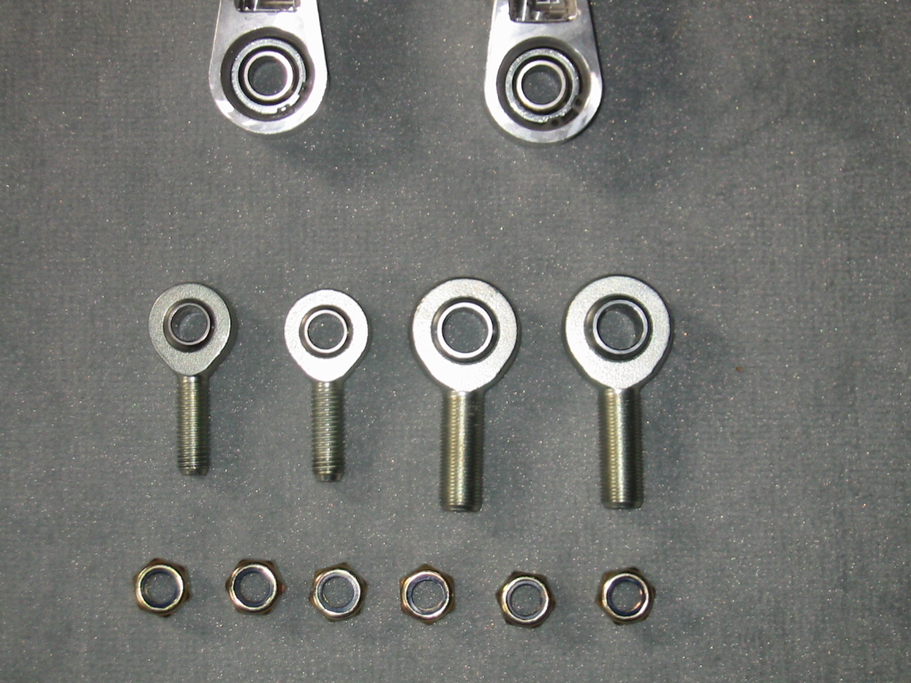
control arm parts: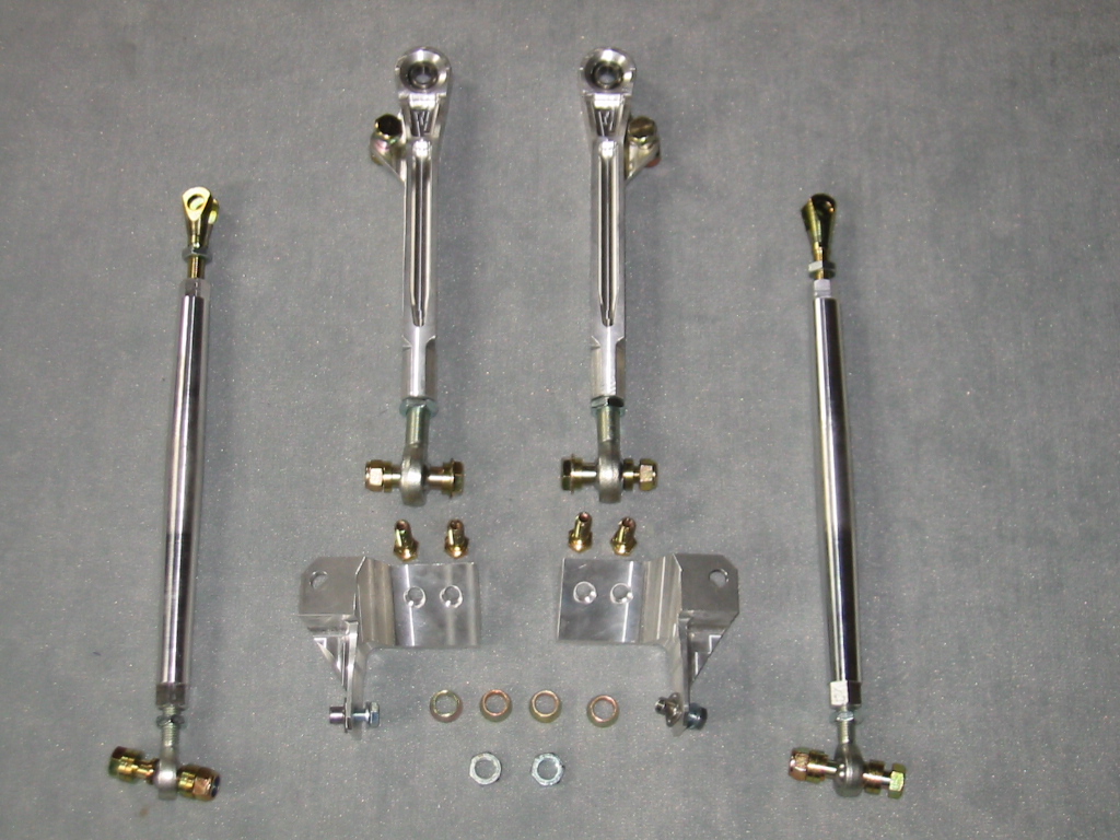
look here for more suspension pictures:
http://gallery.s14power.com/thumbnails.php?album=3
Please note that the control arms are SIDE specific -- in contrast to some earlier setups which try to be universal meaning that they try to fit them to both sides (which is not optimal).
Assembly of Group A/DTM Front Axle E30/36
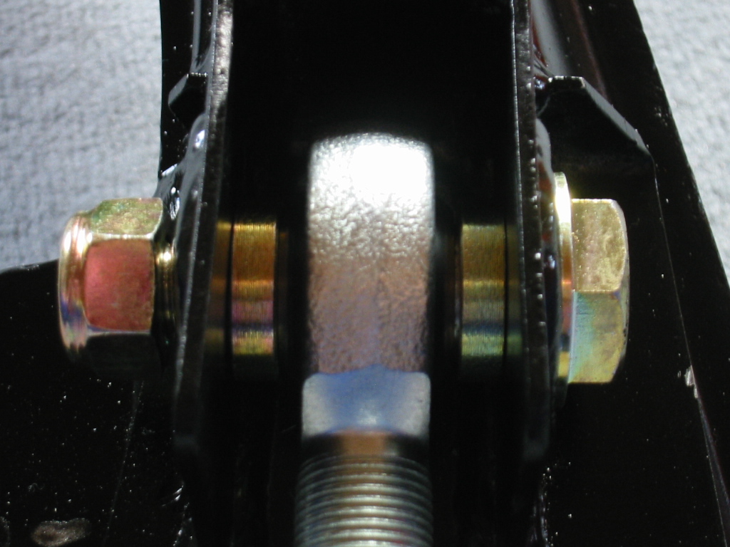
The control arm must be attached to the clevis on the front subframe using spacers as shown in the picture above. The spacers ensure that the control arm's inner rod-end is correctly centered in the clevis.
Torque: 100 Nm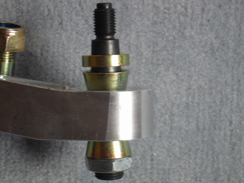
The control arm's outer joint is mounted using conus bearing as shown above. The mounting position can be adjusted using the supplied spacer. Installation of the spacer is not absolutely required.
Torque on bottom nut: 90 Nm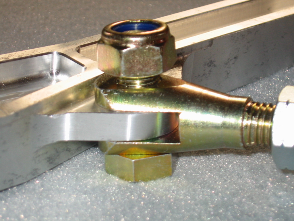
Installation of the fork on the radius arm and attachment to the control arm is shown in the above.
Torque: 100 Nm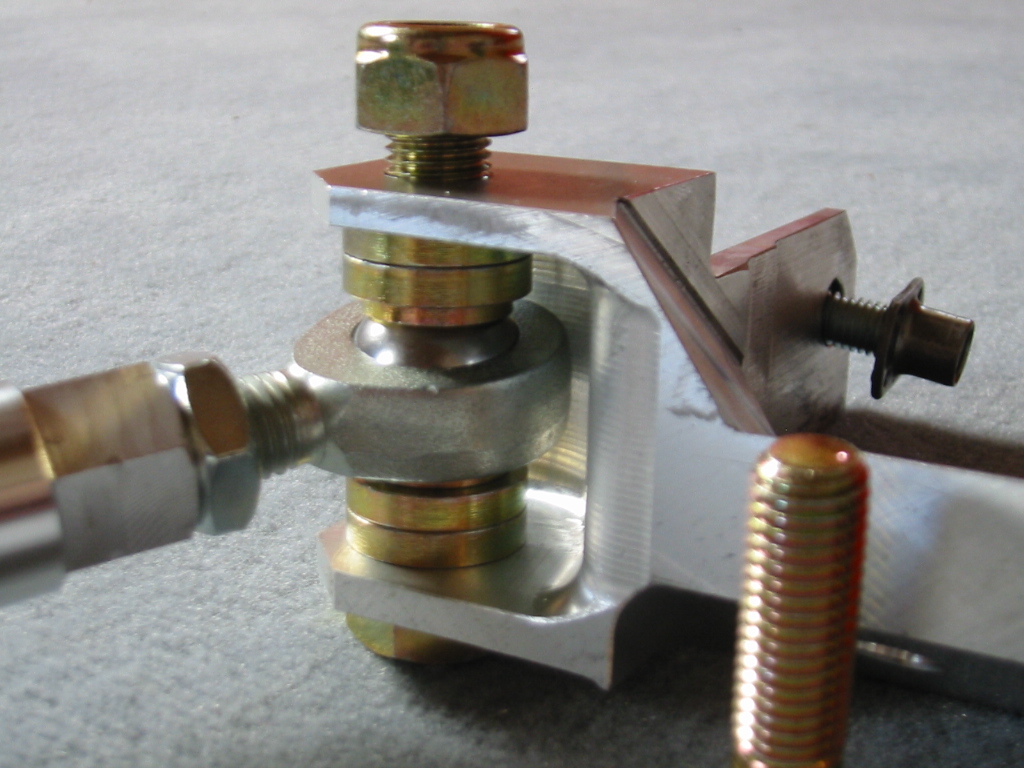
Installation of the radius arm rod-end in the chassis mount is shown above. The supplied spacers must be used both above and below the rod-end to ensure proper clearance under all conditions.
Torque: 100 Nm
With the large spacers it is possible to adust the height of the radius arm and thus change the vehicles anti-dive characteristic. Moving the arm up results in less dive and moving the arm down in more dive when the car is braking.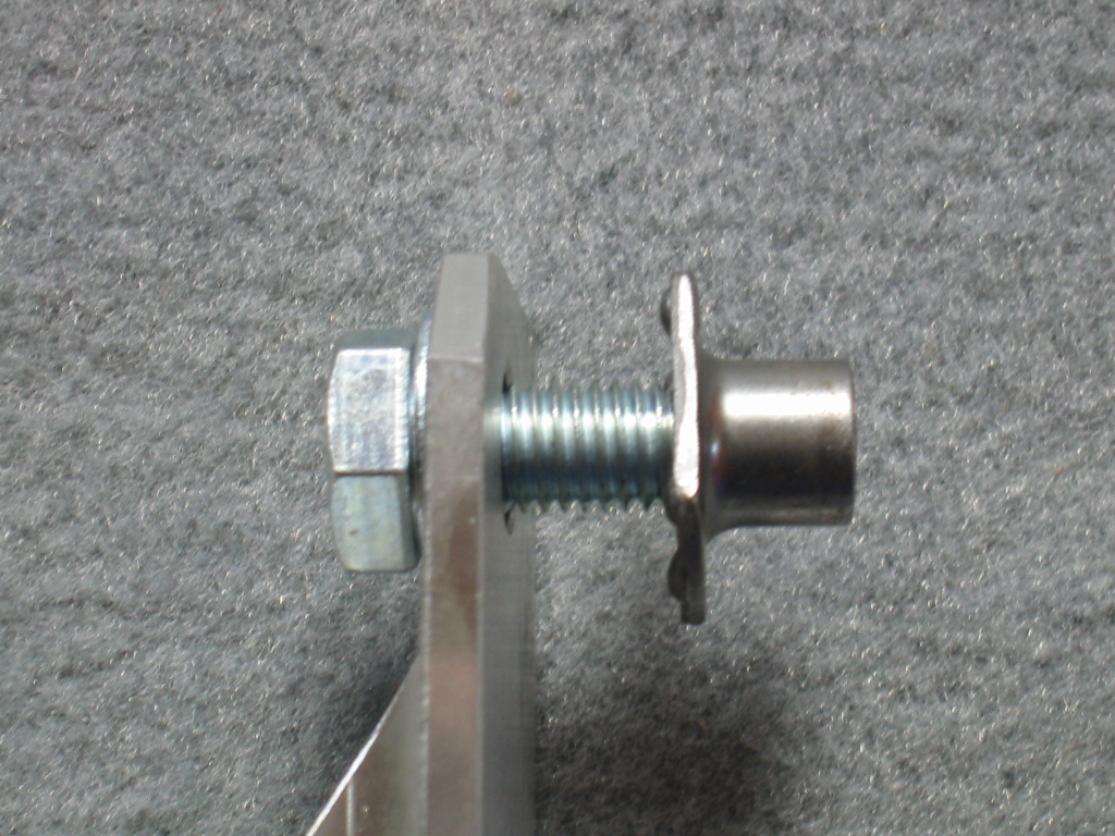
In order to secure the chassis mount which accepts the radius arm a hole must be drilled and the supplied threaded nut welded into the chassis rail.
Ø 12.5 mm.
Torque 42 Nm
E30 only: install a spacer between weld-in nut and chassis mount.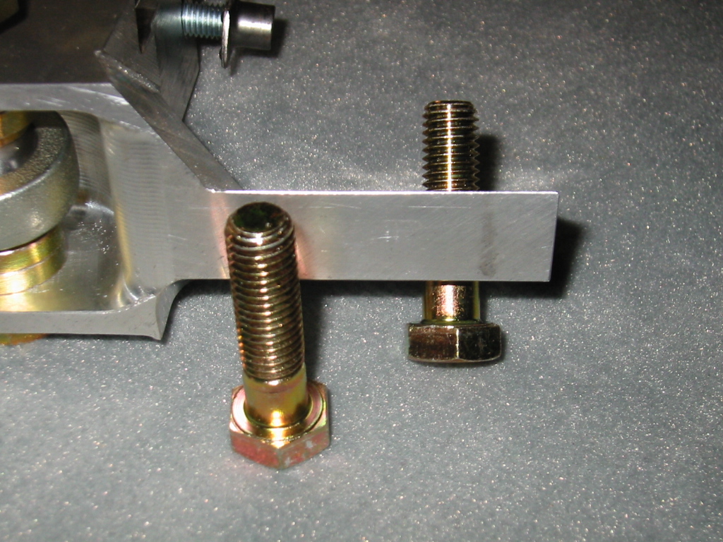
Use the supplied screws M12x1.5 to attach the other points of the radius arm mount to the chassis. The existing threaded holes in the chassis must be enlarged.
Torque M12 screws: 105 Nm
It is possible to use longer screws with stock thread size if desired (not supplied).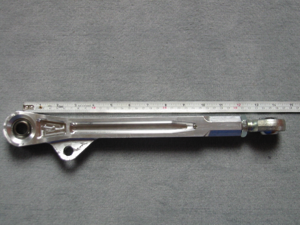
In order to achieve the stock wheel position, the control arm is adjusted to a length of 340 mm measured center to center between the bearing ends.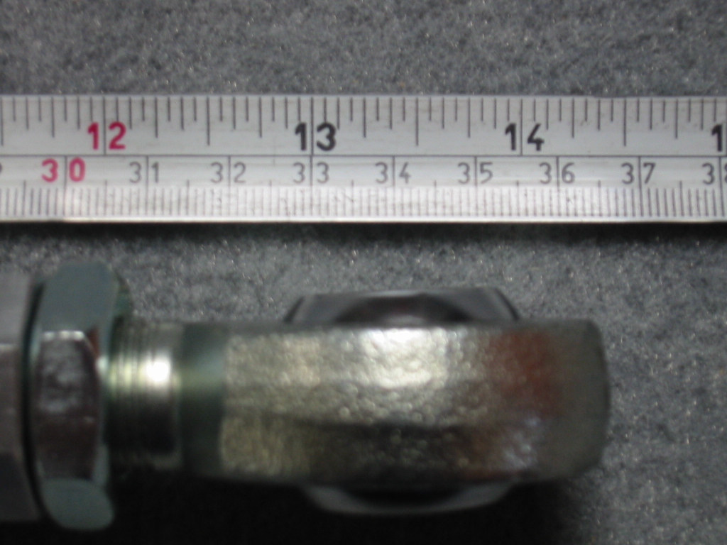
Zoomed picture from above showing the control arm measurement.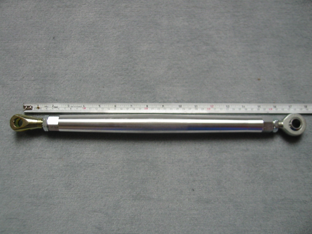
In order to achieve the stock wheel position, the radius arm is adjusted to a length of 435 mm measured between the center of the fork bolt hole and the rod-end center.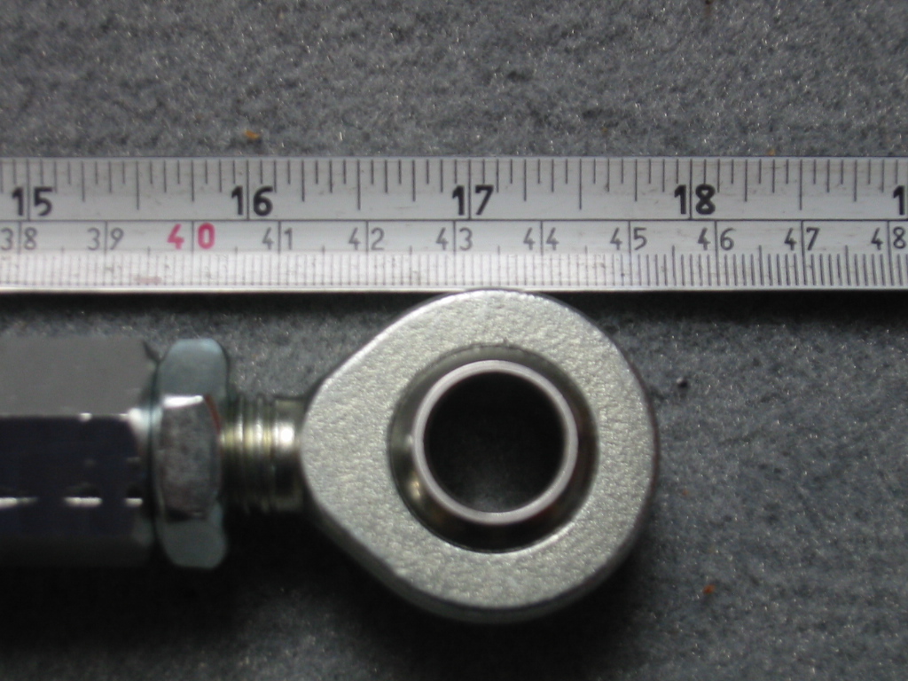
Zoomed picture from above showing the radius arm measurement.
Note that this is just a basic setting to give you a start. From here, you may want to increase the trackwidth and camber by adjusting the control arm outward. The chamber change is in addition to whatever change your adjustable camber plates will allow. This change in trackwidth will not change your scrub radius (this is the distance between the projection of your strut and the center of the wheel). By contrast, if you add a thicker wheel spacer you will increase your scrub radius.
Furthermore, there are different bump spacers (also sometimes called "ackerman" spacers) available. This attaches between the bottom of your strut and the steering knuckle. On a very low car, you will most likely want to use a 25 mm spacer.
There is also a reinforced (ribbed) slightly altered pickup steering knuckle available (Im running a set of these on my current struts).
I dont have pictures yet, but there will also be a conversion for the steering rack and tie rods using rod-ends and a clevis mounted on the steering rack. Very similar to what BMW Motorsport did on their DTM steering racks.
PS: there is also a PDF file available here for download:
http://s14power.com/docs/grAachseE.pdf
JohnKeywords: DTM92 Type Front Suspension


;)
;)
;)


-
- Author
Said 
Registered: September 2011
Posts: 32Comment Date: Tue July 3, 2012 hi john, can't see pics, would like to download the PDF, but no success..
can you send me a private message with the price?
thanksProfile

Powered by: PhotoPost Classifieds
Copyright 2014 All Enthusiast, Inc.
Copyright 2014 All Enthusiast, Inc.
